Carmen A. Brutico III
Construction Management

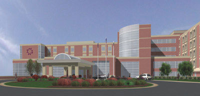
Monongalia General Hospital
Morgantown, WV

![]()


![]()


![]()

![]()
| Note: While great efforts have been taken to provide accurate and complete information on the pages of CPEP, please be aware that the information contained herewith is considered a work‐in‐progress for this thesis project. Modifications and changes related to the original building designs and construction methodologies for this senior thesis project are solely the interpretation of Carmen Brutico. Changes and discrepancies in no way imply that the original design contained errors or was flawed. Differing assumptions, code references, requirements, and methodologies have been incorporated into this thesis project; therefore, investigation results may vary from the original design.” |
General Building Data Building name: Hazel Ruby McQuain Tower Location and site: 1200 JD Anderson Drive
Morgantown, WV. 26505
Building Occupant Name: Monongalia General Hospital Occupancy or function types (type of building): Primary Occupancy: Institutional, I-2
Construction Type: 1-A
Size (square feet):   Existing = 205,000
                                  Renovated = 95,000
                                  New = 210,000
Number of stories above grade: Tower Addition - 6 stories / 5 floors Primary project team: Owner: Monongalia General Hospital
www.monhealthsys.org
Architect: FreemanWhite, Inc.
www.freemanwhite.com
Construction Manager: Turner Construction Company
www.turnerconstruction.com
Mech. Elec. Plum.: FreemanWhite, Inc.
www.freemanwhite.com
Structural: Atlantic Engineering Service
www.aespj.com
Civil: Alpha Associates, Inc.
www.alphaaec.com
Interiors: FreemanWhite, Inc.
www.freemanwhite.com
Fire/Sprinkler: FreemanWhite, Inc.
www.freemanwhite.com
Dates of construction:   Start of  Excavation – June 2006
                                             Completion of  Structure – June 2007
                                             Start Renovations  – October 2007
                                             Building Closed  – December 2007
                                             Start 3rd  Floor Renovations – July 2008
                                             Start 2nd  Floor West Renovations – August 2008
                                             Start Patient  Floor Renovations – August 2008
                                             Construction  Complete – October 2009
                                             Project Closeout  Complete – December 2009
Cost information: Project delivery method: Design-Build Architecture design and functional components: The tower adds 88 new patient rooms for a combined total of 189 beds. The fourth and fifth floors will each have 36 beds divided into sections of nine beds. Each section will include a separate nursing station. All rooms in the existing building will be renovated to become private rooms with handicap accessible restrooms. The new tower will also house the hospital’s many departments from administration to radiology. Building envelope: Major national model codes: Building: IBC – 2000
Mechanical: IMC – 2000
Electrical: NFPA 70 – 1999
Plumbing: IPC – 2000
Fire: WV Fire Code – 2002
Fuel Gas: IFGC – 2000
Energy: IEGC – 2000
Life Safety: NFPA 101 – 2000
Accessibility: ADA – 1994
Sprinkler: NFPA 13
Primary Engineering Systems Construction Demolition: Support of Excavation: The delivery method for this project is unique in that it is defined as a design-build delivery method but essentially utilized a competitive bidding process to select the construction manager, instead of the usual design-build or joint venture firms. The project began as the owner brought an architect (FreemanWhite) on board early in the design phase to then plan and design the project. The architect holds a Guaranteed Max Price (GMP) contract with the owner. The at-risk construction manager (Turner) for the project also holds a GMP contract but with the architect and not with the owner (Monongalia General Hospital), as in most cases. This is also where the combination of delivery methods comes in to play. The selection for the CM on the project was declared using 70% document completion, justifying a design-build delivery. The construction team was permitted to break ground under contract of the 70% complete documents. As mentioned, the selection of the CM was done through a competitive bidding process often used in design-bid-build delivery methods, making the delivery method on this project a unique combination of delivery methods. The architect performed most of the design elements such as architecture, MEP, interiors, and fire and sprinklers. The structural and civil design work, were contracted out by the architect, to third parties engineering companies. The two firms are illustrated on Figure G.1 with their contracts most likely being lump sums. The CM holds all the contracts with the performing construction companies. The five major subcontractors are shown in Figure G.1. All of the subcontractors hold lump sum contracts with the CM. The requirement for subcontractor selection was a minimum of three bidders per scope package. Each of the subcontractors was required to provide their own performance bond and insurance. Additionally the CM held its own general liability insurance.
In addition to housing the mechanical equipment, the new central plant also holds most of the electrical equipment with three rooms designated specifically for normal power, emergency power, and generators. The normal operating electrical system uses a 480V, 5000A switchboard unit. Backup power is supplied by two 1500 kW generators through a 480V, 8000A paralleling switchgear. The generators are connected to their own battery pack for instant generator start up. Each battery pack has its own battery charger located in the generator room, to insure proper charging at all times. The majority of the lighting in the hospital is fluorescent bulbs housed in 2x4 or 2x2 recessed fixtures to match the 2x4 acoustical ceiling tile grid. In order to handle the large HVAC loads required in a 210,000 sq. ft. hospital building, a new central plant was built to house most of the mechanical equipment for the new tower. The large HVAC loads require the use of seven variable air volume roof-top units, each sized specifically to the type and sizes of the areas they serve. Located on the roof of the central plant are two 500 ton, 1,500 GPM (gallons per minute) cooling towers, with reserved space for the possible addition future chillers. Inside the plant are two 500 ton, 1,500 GPM water-cooled chillers and one 5,175 lb/hr, 100 psi steam boiler. For winter heating the building uses a number of different heating units depending on space use, most of which are supplied by hot water from the new boiler. The main heating system for the new tower is a combination of constant air volume and variable air volume terminal reheat units. The constant volume units control the hot water supply to the heating coil in order to control temperature. The variable air volume units control the air supplied to the space via dampers, as well as the hot water control valve, for more control over the space’s air conditions. A dozen hot water baseboard heaters are also used in a few small public spaces. Electric duct heaters were used in the renovated areas of the existing building.
Cast in Place Concrete: Structural Steel:
Fire Protection The building uses a combination of wet and dry pipe sprinkler system for fire suppression. The HVAC system has a multitude of safety devises such as fire and smoke detectors and dampers. An intense amount of smoke detectors are used throughout the hospital to ensure quick detection of a fire. The new tower has two sets of elevators for a total of 5 elevators. The public elevators, consisting of three elevators, are located in the north-east corner of the new building, right off the main entrance lobby. These run from the first floor to the existing tower’s sixth floor, also providing access to the new tower’s roof. The staff elevators, consisting of two elevators, are centrally located in the new building, with a third shaft in place for future elevator use. These run from the first floor to the roof in order to access the elevator penthouse and roof-top air handling units.
Being as the building is a hospital, the communication system is quite extensive. The hospital uses a mix of nurse call systems, intercoms, cameras, telephones, data, and computer systems to operate and manage the operations of the hospital. The large use of equipment throughout the hospital also requires a large amount of receptacles, some of which involve non-typical outlets and power supply for specialized hospital equipment. |